

    and tool cases (blue and yellow boxes) located between the two optical support structures.")
|
I made this Newtonian binocular to complement the 22".
It's smaller and easy to set up for travel to remote observing sites.
The
22" is permanently located at home in its enclosure on the deck.
The 14¼" separates into six parts: two
mirror cells, two optical support structures (i.e., tubes), the
altitude platform (C-ring bearings and interpupillary distance...or
IPD...adjustment carriages), and the azimuth
platform (azimuth bearing and ground plate). They all fit
in my minivan.
Setup takes about a half-hour. While each telescope
holds collimation well between trips, minor co-pointing adjustments are
usually required.
My binocular is
co-pointed
when its two optical axes are close enough to being parallel that their two images
can be fused into one by our visual system. Co-collimated is a
sometimes used term
instead of co-pointed.
The easiest way to design something this complex is with 3D CAD modeling computer software.
I used DesignCAD 3D Max by IMSI.
A CAD model is a virtual representation of the real
telescope, and can be used to generate control files for CNC machines
and laser cutters.
|
 ") |
To date, my metal telescopes have all required machine shop work
— computer numerical control
(CNC) milling or welding. When you make metal telescopes using these
fabrication methods, you have more design flexibility, but your costs are higher.
With the 14¼" binocular's design, I minimized CNC milling and welding
costs by using a few appropriate alternative technologies:
|
   |
Most of the parts of the binocular are made from
modular framing. I ordered pre-cut framing — and
related
parts — from
80/20 Inc., a national manufacturer.
"...[Modular] framing consist[s] of aluminum profiles, fasteners, and
accessories that fit together to make virtually anything..." (from the
80/20 Catalog). Opening the 80/20 shipment for my binocular reminded me
of a Christmas when I unwrapped my favorite toy, a Gilbert
Erector set.
The
heart of the 80/20 system is the T-slot extrusion, or profile. T-nuts
slide into slots in the profile; these nuts are used with screws and
fasteners to combine various parts and build frame structures. The profile shown here is 1" x 1".
The cuts are extremely precise and
the fit of the parts is excellent. Parts are anodized either aluminum or
black.
|
 |
The tertiary assemblies —
one is shown at the left — and secondary holders are printed from ABS plastic. ABS is a tough, impact-resistant, machinable plastic.
3D printing is a natural adjunct to 3D CAD: the file
needed to drive a 3D printer is usually generated directly from the model
created in CAD software. I've been designing telescopes with CAD
since 1992. I was over the learning curve and anxious to try 3D
printing.
3D printing technology has been especially
attractive to the hobbyist and the consumer marketplace. However, a
desktop 3D printer with good resolution can easily cost over $1,000
(US).
Since I didn't want to buy a 3D printer, I contracted these parts from a commercial
3D printing service bureau,
Solid Image 3D, Inc. They use a
high-end
industrial
Stratasys
3-D printer to create ABS parts using
fused
deposition modeling. Accuracy can be held to deviations of no more
than +/- .001" from the submitted CAD model.
I ordered my 3D parts with a resolution of .01", which was accurate
enough for my purposes. Because the parts were made from a file
that I exported from my CAD program and emailed directly to Solid Image 3D,
there were minimal setup costs. Production took only a few hours, so
turnaround time was almost overnight and costs were far below what I
would have spent on my own 3D printer.
An eye-opening article from
Scientific American describes the current state and future of
3D printing.
|
 |
Metal bending, or press brake forming, is a
precision process that takes sheet metal parts...usually laser-cut...and
bends them into three-dimensional structures.
Watch this YouTube
video showing a laser jet cutter. A similar machine cut the cell
triangles used in the binocular.
|
|
|
Watch this
YouTube video showing a water jet cutter. A similar machine cut the
binocular's C-rings.
^To top
|


|
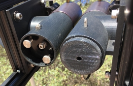
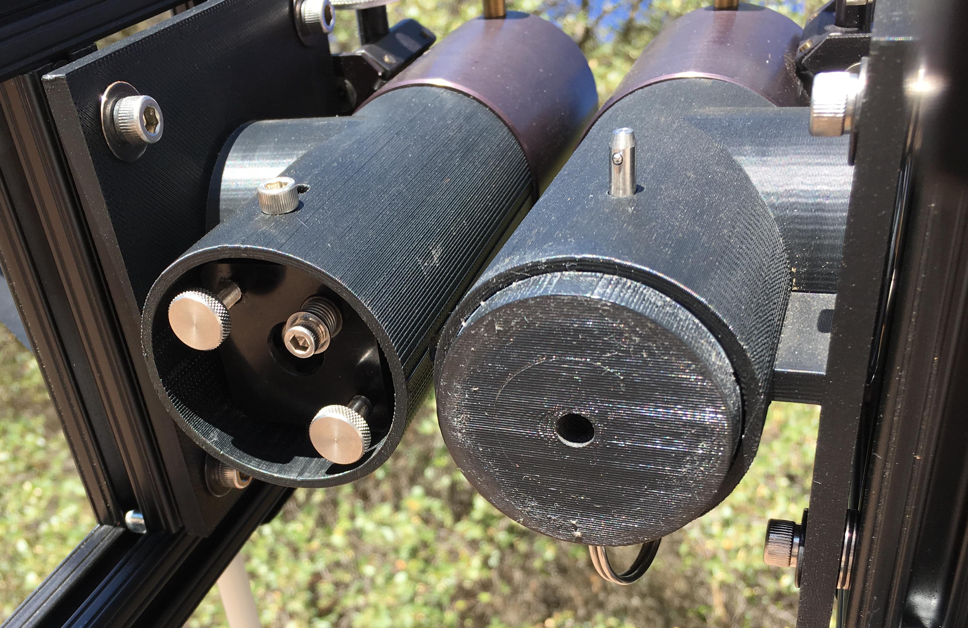
A prominent feature of the binocular's design is a
pair of L-shaped aluminum struts that support both the upper end optics
and the mirror cell. The OSS rests on four bolts in the underlying IPD
carriage and is held in place with brass thumbnuts. Round light baffles
cut from 0.0625" thick acrylic plastic are mounted on the secondary holder.
The entire OSS is one structural piece. The only
moving parts are the focusers. The removable primary mirror cells are
held in place on the OSS and collimated with thumb nuts. Co-pointing
adjustments are made with nuts that hold the OSS to the altitude
platform.
^To top
|
. This image is annotated with the basic parts.")
 |
The mirrors are glued to the cell's pads with RTV, or silicone cement (Dow
Corning Multi-Surface Adhesive Sealant).
Each 18-point whiffletree consists of eighteen pads (inverted weld nuts), six triangles, six
rod end ball joints, three pivot bars and a base plate.
Three bolts attached to the cell's base plate lower onto the OSS. Nuts on the
three cell bolts are adjusted up or down for collimation. The cell is held down
by a central bolt with a thumbnut attached underneath the OSS.
The primaries are protected by a white acrylic plastic lens caps that
fits over the mirrors. Soft rubber trim around the cap's edge rests on
the mirror's edge, so the cap both protects the optical surface and
blocks dust accumulation and moisture buildup.
The mirror cell's parts are all rust-resistant. This makes it easy to
place the mirror in the laundry sink and wash it down.
^To top
|

 |
The spiders for the 14¼" were laser-cut and machine- formed from 0.025"
thick blue tempered spring steel (similar to the steel used in binder clips).
The spiders are positioned accurately by moving them up and down in
their T-slots. Each secondary mirror can be adjusted axially by loosening
a thumbnut and rotating the mirror; laterally by loosening a nut and
tilting the secondary holder in or out.
Light baffles, cut from 1/16" acrylic plastic sheets, are
attached directly to the secondary mirror mount. They are in the light
path; a compromise made to avoid a heavier and more complex upper end.
For travel, I remove the baffles and cover the
secondary with polyethylene shipping tubes.
^To top
|
 

 |
Each tertiary assembly's printed part is attached to cross-pieces in the upper end of
the OSS. It is aligned co-axially with the JMI RCF-1 2"
focuser. The tertiary mirror and focuser are both attached to the
printed part.
One of the tertiaries is adjustable. An
Edmund Optics 1-1/2" small mirror mount is located inside the bottom of the
printed part. I use it to correct any small co-pointing misalignment
errors. This adjustment complements the
primary adjustments built into the altitude and azimuth platforms
(described below).
The tertiary assembly is made from two ABS plastic 3-D printed
parts. Its design includes baffling and eliminates stray light
incursion.
For travel, I insert polyethylene shipping tube plugs
into the focusers and the ABS plastic printed part. These prevent the
accumulation of dust on the tertiary mirrors.
|

|
I use larger 2" eyepieces because they have larger real fields and longer
focal lengths. I use these eyepieces:
|
BW-OPTIC Ultrawide |
30mm |
60X |
1.3 deg.
FOV |
| Explore
Sientific 70-deg. Series |
25mm |
72X |
1.0 deg.
FOV |
| Tele
Vue 22mm Nagler type 4 |
22mm |
82X |
1.0 deg.
FOV |
| Tele
Vue 16mm Nagler type 5 |
16mm |
113X |
0.7 deg.
FOV |
| Tele
Vue 9mm Nagler |
9mm |
201X |
0.4 deg.
FOV |
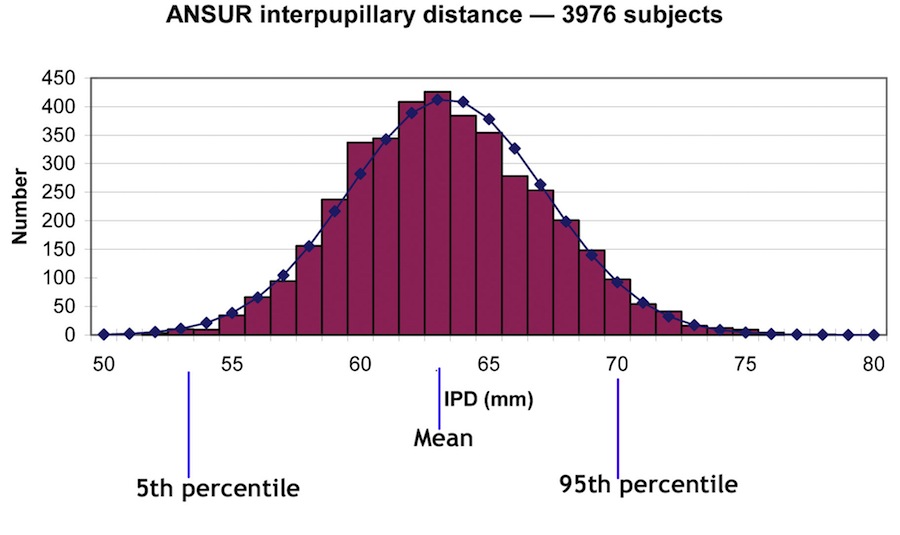
Some of these eyepieces are so
wide they
can't be used by people with narrowly-set eyes —
even if they're touching. My Tele Vue 22mm Nagler is 58mm
across, and the exit pupils in a pair would be too far apart for about 8% of
the population (see the chart to the left).
The minimum IPD that is supported by the 2" focusers
is 57mm, or about the 7th percentile of the IPD distribution.
Barrel diameters of 1¼" eyepieces are smaller, and virtually all
adults and most children can use them when mounted in 1¼" focusers.
^To top
|
 
   |
This component combines the altitude bearings and the
interpupillary distance (IPD) carriage. C-rings attached to
the rectangular frame ride on four ball bearings in the
azimuth platform.
Adjustable Teflon clutches on two of the altitude bearings keep the
telescope from falling.
Ball bearings — instead
of plastic laminates and Teflon pads —
provide a much smoother and less resistant movement for a push-to
telescope. The Teflon clutches need only be tightened or loosened when
changing between pairs of eyepieces with significantly different
weights.
Two IPD carriages are attached to the altitude frame with linear
friction bearings. To adjust IPD, the user rotates a knob just below the
eyepieces. Turning the knob causes the carriages —
one supporting each side's OSS —
to move both telescopes laterally and in opposing directions. The
mechanism uses a right-angle bevel gear drive to translate the knob rotation into
two lead screws attached to each carriage.
Counterweights attached to the bottom of the frame balance the
telescope.
The carriages also provide independent co-pointing
adjustments for optical parallelism between the two telescopes.
Collimation is unaffected. Each OSS is connected to its underlying IPD carriage through bolts and
adjusting nuts. Co-pointing is achieved by raising or lowering the nuts
until the separate images from each side can be visually fused. This is
the primary method of adjusting for co-pointing; a secondary adjustment
can be made with the Edmund mirror mount attatched to one of the
tertiaries.
The most difficult challenge in building any large
binocular telescope is making its mount so stiff that co-pointing errors
less than a few arcseconds apart don't happen. This sounds like an
ambitious goal. Is it really necessary?
In theory, the resolution of a 14.25" mirror can be
estimated as 4.8/14.25, or .33 arcseconds. Mars in October 2016 is only
8.1 arcseconds in diameter. With good seeing, it's easy to see two unfused,
overlapping images if they're only one arcsecond apart.
The binocular's IPD adjustment involves no change to the focal
plane or upper end optics positions. Taking the IPD adjustment out of the optical path
simplifies and lightens the upper end structure. This eliminates the
errors in collimation or co-pointing that binoculars designed with moving tertiary assemblies or
rotating upper cage rings can introduce.
I used this same approach in the design of
my
12.5" binocular.
It's like hand-held binoculars: each half moves with no optical path
change when you bend them.
^To top
|


  |
The upper part of the assembly contains the altitude bearings and
houses the digital setting circle components. The upper part rotates
over the lower ground board, a rigid structure made from a 2" x 2" aluminum
80/20 profile with bracing at
the joints.
The bottom of the rotating upper part and the top of the ground board are
cut from ½" 6061-T6 aluminum plate. These two
parts are held together with a heavy shoulder bolt and a small thrust
bearing.
The two plates sandwich a large-diameter, ring-style aluminum
turntable that is attached to the rotating part. An azimuth clutch, made from a Teflon friction block, prevents the
telescope from sailing. A knob mounted on the upper plate adjusts the
tension.
^To top
|


|
The telescope doesn't have a drive system, but uses a
digital setting circles system to provide a manual push-to target. The
system consists of:
-
Encoders that
measure movement in the altitude and azimuth directions
-
Decoder circuitry that converts and
tracks encoder pulses to digital position counts
(sometimes called ticks)
-
Wi-Fi hot spot that communicates
the counts wirelessly to a iPhone
-
SkySafari planetarium app.
Encoders
A pair of
U. S. Digital S5-1024 optical shaft encoders are mounted on rollers
that track the altitude and azimuth bearings. These rollers gear the
number of pulses up to 33,125 for a complete revolution in the azimuth axis, and 52,890 for the
altitude axis. Mounting encoders this way avoids the difficulties of
placing them exactly on the telescope's axes.
These high counts are achieved without expensive
high-resolution encoders, but with equivalent results at the system
level. The Nexus-II can accept high
rates of encoder input without dropping pulses.
Nexus-II decoder
The encoder pulses are decoded to
digital positions in an
Astro
Devices' Nexus-II implementation of the Tangent Instruments BBox protocol.
The Nexus-II has a fast processor, which permits a 10 per second readout rate
for a
smooth-moving SkySafari chart on the iPhone.
The Nexus-II's encoder jack is
connected with a flat 8-conductor cable to the RJ-45 jack of a small modular surface mount box,
typically used in telephone cabling installations. The surface mount
makes it easy to connect the eight leads from each of the encoders to
the appropriate pin of the outgoing RJ-45 jack.
Wi-Fi hotspot
The
Nexus-II then passes the binocular's position through its integrated local Wi-Fi hotspot to an iPhone running Southern Stars'
SkySafari
planetarium app. The app converts the position counts to sky chart
coordinates and shows the telescope's location.
SkySafari planetarium app
Once the SkySafari app is connected to
the digital setting circles and is aligned with two objects, it shows the binocular's reported position
with a planetarium display of surrounding objects. As I push the binocular around the sky, SkySafari follows its
position by moving the bulls eye against the display. Once I close in on
the selected target, I can zoom in the display to gain higher resolution. When the bulls eye
is centered on the target, I'm ready to view it through the binocular.
I can also use SkySafari on my iPad to
create a larger, more panoramic view of what's happening at the
telescope.
SkySafari is a superb program. It simplifies
selecting and locating interesting objects in the context of a rich, interactive
and high-resolution chart of the night sky. For most objects, it goes
beyond a pair of numbers on a red alphanumeric LED display, or
star-hopping with charts.
^To top
|
|
|
|
|
|
The 80/20 and all milled or cut aluminum parts are anodized black.
The 3D printed parts are made with black ABS plastic. The spiders are
powder-coated with a black, textured semi-gloss paint (Cardinal
C241-BK01).
I used stainless steel screws to provide
corrosion resistance. Stainless steel parts are used exclusively. The
telescope can withstand a damp night.
Some yellow trim outlines the major 80/20 assemblies to relieve the
black boredom.
^To top
|

 |
Bill Thomas, a fellow
foothills ATM, made the primaries for the binocular. Bill's focus
is mirror making; he has developed the
Slit Image Test,
which combines the best of the Lateral Wire Test (LWT)
and the Caustic test. The two mirrors have Strehl ratios of .98 and .97,
or at least 1/10 wave. Nearly perfect!
The secondary and tertiary mirrors were purchased from
Newport Glass Works.
^To top
|
|
|
|


|
I made five of these binoculars, three in collaboration with the
Three Rivers Foundation (3RF) in Texas and Australia. First light came in 2003 and the last upgrades were completed
in 2010.
When used at home, my binocular sits on an isolated concrete
pier in the middle of an observing deck, and is protected by a roll-away enclosure that can be completely removed from the deck.
For travel to dark sky sites, I dissemble it into pieces — none heavier than 60 pounds — and lift
them
into the back of my Toyota Sienna minivan without ramps or wheelbarrow attachments. This approach sacrifices rapid setup for easy lifting by someone with less than a Herculean back
and no trailer.
Key features:
-
22" f5 Newtonian binocular telescope on an
alt-az mount
-
9½' tall, with center of gravity 16" above ground to
minimize eyepiece height
-
Economical use of materials through a minimalist design
-
338 pounds total weight, including lead counterweights
-
48 pound, 1⅝" thick primaries, 4½" secondaries, 2"
tertiaries
-
Mirrors are glued to triangular cells to simplify cell
structure
-
Strut tubes are only ⅝" in diameter, and use midpoint bracing
to prevent sag
-
Spiders are made with 12 strands of .02" wire
-
C-rings (or trunnions) are mounted inboard to minimize azimuth and ground ring
diameter
-
Adjustments to converge both sides into optical parallelism are
separate from — and do not compromise — collimation
-
2" eyepieces are supported with a wide range of interpupillary
adjustment
Here are the contractors and suppliers I used:
^To top
|


|
A lightweight
welded steel hexagon ring holds the secondary, tertiary, interpupillary adjustment and a slightly modified Jim's Mobile, Inc.
RCF-1 2" focuser. Bracing keeps the
focusers from sagging and the ring from warping.
The user turns a knob to move both focusers closer together or farther apart for IPD adjustment. After adjusting IPD, the user focuses each
side individually.
This approach to focuser mounting in a Newtonian binocular minimizes top end weight and avoids collimation or
co-pointing issues that may
happen with
rotating upper end cages. However, it does require the user to re-focus
whenever the IPD setting is changed.
The two focusers are joined for a single interpupillary range of 57–75mm. The 2" RCF-1 focuser tubes restrict minimum IPD to 57mm, providing
the eyepiece barrels being used are no more than 2⅛" inches in
diameter.
The tertiaries are located at the ends of the focusers.
Two light baffles are attached to the sides opposite the secondaries and one in the middle under the focusers. The baffles are made from vinyl-coated artists
foam board. They add virtually no weight to the top end and are moisture-resistant.
I favor 2" eyepieces because they provide larger real fields and longer focal lengths for optimized viewing at lower
magnifications. The binocular supports a wide range of eyepieces using the 2" focuser and a 1¼" adapter. I use these
Tele Vue and BW-Optik eyepieces:
| Type |
Focal length (mm) |
1¼" or 2" |
Appar- ent field (deg) |
Field stop diameter (mm) |
Widest part of eye-
piece
(mm) |
Magni-fication |
| Nagler 4 |
22 |
2 |
82 |
31.1 |
61 |
127 |
| Nagler 4 |
17 |
2 |
82 |
24.3 |
61 |
164 |
| Nagler 5 |
16 |
1¼ |
82 |
22.1 |
43 |
174 |
| Nagler 6 |
9 |
1¼ |
82 |
12.4 |
41 |
310 |
|
BW Optik |
30 |
2" |
80 |
41.1 |
57 |
93
|
|
|
 
|
Wires hold the secondaries in place (Type 302/304 stainless steel, 0.02" diameter, spring
tempered bright wire). Twelve strands connect three eye bolts in the hexagon ring to six eye bolts in the secondary holder. Although
the resulting web introduces more diffraction than a simple three- or four-vane spider, its diffraction pattern is more diffuse, less noticeable and the web is much more rigid in all directions.
The spider's central assembly permits precise adjustment of the 4½" secondary mirror in the
mechanical and optical axes of the telescope. Before I added these adjustments, I couldn't be sure that these two axes coincided. When they
didn't, eyepiece positions were offset either horizontally, vertically
or both.
To compensate for this, the user had to unnaturally tip or rotate his or
her head. This sort of adjustment is unnecessary in smaller binoculars,
but with a 22" f5, eyepiece misalignments
like these are magnified noticeably and are irritating. The secondary's mount
consists of a central ⅜" threaded rod, an adjustment assembly and a five-point mount glued to the 4½" secondary. A ⅝" tube suspended in the
wire web holds
the threaded rod. This permits vertical and lateral positioning
of the secondary. Three machine screws tensioned with compression
springs collimate the secondary.
Two-inch
minor axis tertiaries are mounted on an
Edmund Industrial Optics mirror mount. The mount has thumbscrews that collimate
the tertiary, and the tertiary can be moved laterally so its mechanical axis coincides with the optical axis.
A
Rigel Systems
QuikFinder red dot
sight is mounted on the top
end.
^To top
|
  
  
|
To provide its 24" footprint, the mount's C-rings are located between the mirrors rather than outboard. The
mirror mounts are cantilevered in an open structure and are designed to minimize flexure and promote air movement.
Four lead brick counterweights
placed on shelves between the C-rings balance the telescope around the altitude axis.
The mounts are triangular instead of the usual square shape. This
both simplifies construction of both the mount and the cells, stiffens
the mount, and matches the six-strut tube structure.
For setup, each tube is assembled from
six separate struts, a hexagonal strut brace, a top end, and a cell. Mounting blocks in the top and bottom ends hold each ⅝" aluminum
strut. Thumbscrews and tube connectors lock each tube in place. O-rings placed between the struts and
their mounting blocks eliminate vibrations transmitted through the struts. A hexagonal brace half-way up the struts prevents tube sag.
Adjusting nuts on three threaded rods mounted on the mirror cells collimate the primaries; they move the tubes relative to
the mirrors. Separate co-pointing adjustments, used to make the optical axes of both telescopes parallel, are also located on the same threaded
rods. Thus, co-pointing the binocular won't affect collimation of either side.
^To top
|
 attach to one corner of the flex rocker. The electronics include the Sidereal Technology controller, battery and hand pad.")  
  
|
The binocular uses a drive system based on the
Sidereal Technology servo motor controller. The drive motors, gearheads, encoders and
clutches are mounted on a drive frame. Direct, friction-roller drives move the telescope in each axis.
Brushed DC servo motors with gearheads from
Dynetic Systems are used. They have these properties:
-
NEMA 17 size, 1½" diameter
-
12V DC, 3.25A, 30W brushed servo motor
-
70:1 gear ratio
-
3.6 in-oz output
-
10 arc-min backlash
-
1000 line two-channel indexed optical encoder
-
are powered by a small 12V gel cell
Two
US Digital S-1000 optical encoders
independently sense the telescope's
altitude and azimuth positions and update the servo
controller as the telescope slews or tracks.
The encoders are not mounted at the altitude and azimuth
axes. Instead, spring-loaded friction rollers mounted on each encoder's shaft bear against a C-ring
(altitude) and the inner edge of the ground ring (azimuth).
This arrangement significantly increases the effective
resolution of the encoders and eliminates awkward axial mounts.
Both motors are connected to the palm-sized Sidereal Technology controller. This
remarkably versatile controller, jointly developed by Dan Gray and Mel Bartels, allows automated
tracking and slewing (i.e., go-to) when used with any of the following:
-
an
Argo Navis telescope computer
-
an ASCOM-compliant PC planetarium program
-
Sidereal Technology's
SiTechExe PC application
-
Mel Bartels'
Scope
II PC
application for high precision
control
-
Southern Stars
SkySafari iPhone planetarium app
Finding
the target object is done either by star-hopping with charts or using
one of the programs or devices listed above.
The
controller can also be used in standalone mode, which requires the user to slew manually to the desired object.
Once slewed, the Sidereal Technology controller will track the object. To facilitate manual
slewing, I included adjustable slip couplings, or clutches, by
Polyclutch in the drive train.
The drive frame, or flex rocker, rotates on
a welded aluminum azimuth ground ring. Heavy-duty needle bearings support most of the telescope's weight. A fine diamond pattern is knurled
into the drive rollers to prevent any slippage. The
ground ring, 25" in diameter, is a welded structure consisting of a hexagonal frame sandwiched between two rings, all made from ½"
aluminum plate.
The circular inner edge of the ground ring acts as a raceway for the telescope's azimuth encoder. Idler bearings mounted on the drive frame
also roll laterally against the same edge and define the
azimuth axis. The ground ring rests on triangular feet.
^To top
|
     
   
|
The cell is a traditional ATM whiffletree — built without astatic support levers. Each primary mirror is glued to its cell with
832
Multi-Surface Adhesive Sealant RTV (silicone). This eliminates lateral supports, like slings or clips, and simplifies design.
The cell's triangular base, made from welded ½" aluminum bar stock, supports the whiffletree and the threaded rods used
to attach the struts. I remove the
cell and mirror up off the mount for transportation with a triangular lifter.
The
whiffletree's 27 support points were located using David Lewis'
Graphical Plop
program. The whiffletree's 9 triangles are connected by and pivot on stainless steel, Teflon-lined spherical ball joint bearings. These bearings give the whiffletree flexibility,
while
preventing lateral displacement during use. They are glued with epoxy cement into recessed holes counterbored into the three large triangles
of the whiffletree. The bearings fit snugly, insuring the dimensional stability of the cell regardless of its altitude position.
When not in use, I cover each mirror with a cap made from ¼" white translucent
acrylic plastic. It rests directly on the mirror, but contacts the mirror only at its edge. A soft rubber trim is wrapped around the cap's
edge to avoid mirror damage and
prevent dust from accumulating on the mirror. The cap
can be removed or replaced any time.
No observers who have used any of the eleven 22" mirrors glued with this cell have claimed to have noticed any astigmatism. JMI glues mirrors in their NGT telescopes.
The
Steward
Observatory Mirror Laboratory at the University of Arizona fearlessly uses ordinary RTV to lift 8-meter class
mirrors. Despite these and other examples of successful RTV use, ATM'ers endlessly debate its efficacy.
^To top
|

 
|
Richard Berry
described his observing experience with Lee Cain's 17½" binocular telescope at the 1984 Texas Star Party as
"...defying description: I discovered that the quality and sheer realism, for lack of
a better term, of an image viewed with two eyes greatly exceeds any monocular image I've
seen...on closing one eye, I still had a splendid view, but the subtle impression of the
nebular glow as grainless, smooth, silky, and fluid, and the faint western extensions of
the [Lagoon] nebula, were lost with one eye." (Telescope Making 23, 1984, p.
34).
It's no secret that two eyes can improve deep-space viewing. Twenty-five years ago
Sky & Telescope
published the following:
"Besides feeling more natural and relaxing, binocular vision enhances several areas of visual performance that are important
for astronomical observing. These include increased contrast sensitivity, improved resolution, and the ability to detect fainter objects..."
"Enhanced perceptions in the range of 40 percent are almost too good to be true, yet they are available by just using two
eyes rather than one." ("Binocular Astronomy: Is There a Difference?" by Keith P. and O. D. Bowen, June, 1985, p. 572, Observer's Page)
My 22" binocular has about the same light gathering power as a single 31" monocular (i.e., the area of the two mirrors is 380 sq.
in., the same as a 30.8" monocular). It cost more than the typical 30"
Dobsonian monocular and was more complex to build.
Unfortunately, their cost and skepticism about their benefits —
"too good to be true" — has hindered binocular acceptance among amateur telescope
makers. The notion of binocular superiority is sometimes denied by ATMs
using
a lot of irrelevant information, such as the limiting magnitude of a
telescope, or the absence of parallax at interstellar distances, most of
which has
nothing to do with visual perception.
Such monocular users deny the total systems aspect of a person looking through a
telescope: their thinking stops as soon as light leaves their eyepiece.
They are unaware of the role of our visual
system can play in deep sky observing.
In spite of this, binocular builders insist they're worth the effort.
There's a reason
for this — it's more than
just hype from a community of like-minded Newtonian binocular buffs. The physiological and neural aspects of binocular vision have been studied
for centuries, and much is known about how eyes work together.
While
the major and most known benefit of two eyes is depth perception, or stereopsis, there is another, more subtle benefit
they provide. Stereopsis, or depth perception due to parallax,
plays no role in telescopic observations
— it's all
about binocular summation.
Most benefits of two eyes are obvious: a spare in case of damage or loss of one; a
horizontal view of 180° instead of 150° with one eye; stereopsis, or depth perception based on parallax or retinal image displacement.
Binocular summation, or enhanced acuity and threshold detection levels, is a little-known
phenomenon except to those involved in
ophthalmology, vision science, or binocular telescopes. WikipediA
has a clear and concise explanation of binocular vision and
summation.
Binocular summation has long been investigated and understood by vision scientists (see
Lecture 10 - Binocular Summation lecture
notes from a vision science course taught by
Dr. Thomas Salmon, Professor of Optometry, Northeastern State University, Tahlequah, OK). Studies have shown that visual perception using two
eyes is enhanced over one eye
in several ways:
- Visual acuity
- Visual detection at threshold
levels, including both absolute light detection and contrast sensitivity
- Brightness perception
- Flicker perception
- Form recognition
Experiments show that the binocular detection
threshold of dim light is 1.4 times better than for monocular viewing.
Two theories are proposed to explain this, probability summation and
neural
summation.
Probability summation holds that chances are
statistically better using two retinal receptors instead of one. Neural summation
hypothesizes that some connection between two monocular neural pathways in the
brain might produce a physiological
"sum" of the images. Studies have shown that binocular
sensitivity is well in excess of any gain that would be expected from
probability summation, thus supporting the presence of neural summation.
Regardless of which theory is
correct, binocular summation is always at
work in our neural system, whether we're looking
through a binocular telescope, or a small
hand-held binocular, or a pair of eyeglasses, or
nothing at all. Most of us go through life
without appreciating this property of our vision
system, thinking that two eyes are only used for
depth perception.
Only when we are using our
eyes in the dark and looking at very
dim objects, perhaps only slightly above the
threshold of detection, will we benefit from binocular summation. Amateur
astronomers using binocular telescopes gain this
benefit; those using monocular telescopes miss
out.
|
 |
In effect, the brain adds up both images to reveal more
information, much as stacking multiple exposures in mage processing enhances
the resulting image. If you doubt this, try using the chart on the left with
one eye and then two eyes. You'll probably see a difference in your ability
to detect the dimmer letters. |
|


|
Arie
Otte, an ATM from the Netherlands, has built a 13" binocular
telescope. At the left are his drawings compared to drawings from other
observers using larger monocular telescopes. Arie has also
written definitively about binocular summation from an ATM's viewpoint.
For binocular telescope users like Arie, binocular summation means:
- Objects present more detail (acuity)
- Fainter objects appear brighter (threshold detection)
- Structure in many objects is more visible (contrast sensitivity)
I was interested in determining for myself whether
binocular summation also improved visual acuity. During an appointment with my
ophthalmologist, he tested both eyes, first independently
and then together. My right eye tested 20/40 and my left eye tested 20/30.
Using both eyes — even without glasses — I tested 20/15, a definite improvement.
Besides summation, two eyes provide additional effects. There are other depth perception cues besides stereopsis due to parallax.
Color displacement, or chromostereopsis, makes some things appear in front of others because of their color. The brain may similarly displace objects based on their size and brightness. Although these color and displacement effects are artificial — produced by the brain trying to get depth from the images — they are very pleasing.
Amateur astronomers using my 22" binocular have confirmed the benefits of increased acuity, lower threshold detection, increased
contrast sensitivity, and artificial displacement through these observations:
- Some see more color (e.g., Orion nebula)
- Some see more extensive nebulosity (e.g., Swan nebula)
- Some see more detail (e.g., globulars in M31 look like disks)
- Some see red stars in front of blue stars (as in the Jewel Box cluster)
- Some see nebula behind stars (e.g., as in the Dumbbell nebula)
- Some see more contrast (e.g., in the Omega nebula)
Finally, there is the sheer comfort of using both eyes. Concentration on details and prolonged viewing
is easier without squinting. The brain doesn't have to suppress extraneous
background, as is the case with a monocular telescope.
|
") ") ") ") ") ")
") , 10\" (RB-10) and 6\" (RB-66) with Jim Burr, CEO") ") ")
|
A handful of ATMs have built binoculars over the years.
They all believe that a binocular enhances viewing, based on their
experiences or anecdotal evidence from others. Shown at the left are a few
examples of binoculars from various countries made by those who have seen
the light — with both eyes — as well as commercial models from JMI Telescopes.
^To top
|

|
A binocular viewer also improves visual
observing. Newtonian binoculars and binocular viewers share these
characteristics:
- Natural, comfortable viewing with both eyes
- A sense of presence (not parallax, and maybe not
spacewalk viewing, but definitely spaceship window viewing)
I have no doubt that anyone who invests in a binocular
viewer for a large-aperture monocular telescope will definitely get their
money's worth. Although there is a small amount of light loss due to the beam
splitter, prisms and other lenses (perhaps a half magnitude), the
benefits of using both eyes outweighs this disadvantage.
Some claim the magic of the brain's signal
processing actually improves the monocular view for brighter objects; some
argue it helps at all magnitudes. More information on binocular viewers
can be found in Sky & Telescope, Vol. 104, No. 3, September 2002,
p. 46 and Sky & Telescope, Vol. 109, No. 3,
March 2005 and in a Cloudy Nights review.
A large binocular, however, has these advantages over a
larger viewer-equipped monocular:
-
A binocular gathers 40% more light than the same sized monocular. It takes both eyes to realize this advantage. With a
binoviewer, the light is split equally between both eyepieces, so summation at best only restores part of the light-gathering power of the monocular's
aperture. For example, a binoviewer with a 30" monocular reduces its effectiveness to about a 28" mirror:
a. Half a 30" is equivalent to a 21.2" in surface area
b. 40% summation with two 21.2" mirrors would
produce the equivalent of one 29.7" mirror
c. Light loss of 5% by the binoviewer (my assumption)
would further reduce this to about a 28.2" mirror
A true binocular with equivalent performance would require only 20.1" mirrors.
-
No light is lost, as is the case with the viewer's
extra optical surfaces and prisms (however well-coated)
-
No Barlow lens, also called a corrector lens, is needed, so
there is no image magnification (usually 20% in a binoviewer).
-
A binocular can use 2" focusers, so any pair of long focal length 2" eyepieces can be
used, making magnifications below 100x possible, constrained only by
the maximum diameter of the eyepiece's barrel and the viewer's interpupillary
requirements (e.g., with my interpupillary separation I could use a Tele Vue 41mm Panoptic or 31mm Nagler eyepiece,
but many could not).
-
A binocular does not constrain clear aperture, which means that large aperture-stop eyepieces suffer no vignetting. Most
binoviewers restrict clear apertures to less than 30 mm.
These factors point to significantly better low-power
viewing with a binocular that can exploit modern wide angle eyepieces. I regularly use 30mm, 80° apparent field 2" eyepieces with
my 22" binocular, which
yield 93x magnification (almost as good as a 31mm Nagler). Although there
are 1¼" eyepieces made with focal lengths up to 40mm or more, most are
four-element Plossls and have apparent fields of only 50° or so. While
quite acceptable with binoviewers, they lack the spectacular views
afforded eyepieces in the 80° wide-angle class.
Tele Vue's
longest focal length Nagler with a 1¼" barrel is 16mm. This eyepiece, used
with a 1.2x optical compensator Denk II would yield 209x
magnification on the 22" binocular. With 30mm 2" eyepieces, the 22" operates at less than half that magnification.
^To top
|

|
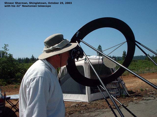
Shingletown shootout, October 24-25, 2003 near Mt. Lassen
In a test conducted October 24-25, 2003 at the Shingletown air strip I was able to compare the 22" binocular to Dan Gray's innovative new 28" string telescope. We
were joined by Shneor Sherman and Mel Bartels, both experienced observers. Our benchmark objects included the NGC 281 edge-on galaxy, the
Andromeda galaxy, the Perseus double cluster and the Great Orion nebula.
Although the seeing was poor, and Dan's temporarily silvered mirror was slightly undercorrected and astigmatic, the
consensus among the group was:
- In general, views were essentially the same.
- The 28" showed slightly brighter star images.
- Contrast and brightness of galaxies and their dust lanes were similar.
- Nebulosity in M42 was equally impressive, and the pink color in M42 was easy to detect in both telescopes.
- The brain much prefers the comfort of binocular viewing — the sense of presence, the silkiness of faint, distended
objects, the ability to concentrate, the removal of "background noise" by the brain were all noted as improvements due to the
binocular view.
-
Low power 95X, 80° field of views were unique to the 22" binocular.
Mel Bartels, in postings from the ATM-list about the Shingletown shootout
"Dan Gray, Bruce Sayre and I spent an entire night comparing Bruce's 22 inch binoculars to Dan's 28 inch scope...with a
22 inch bino, you can achieve a wider field at larger exit pupil than a 31 inch, yet enjoy the equivalent of 31 inches aperture. That's
priceless."
"The Richest Field views of bright and dark nebulae through Bruce's 22 inch were breathtaking - higher contrast than
I've seen in any scope of any aperture; plus don't forget that milky smooth image. That's priceless."
"BTW, the faintest magnitude didn't quite stack up to the simple case of doubling the aperture. Elements of Einstein's
Cross were just a slightest bit more visible in the 28 inch than the 22 inch binocs - say 90% of the way between the 22 inch mono view and
the 28 inch mono view."
Randy Muller, June 26, 2006, Shingletown Star Party
"The best view I had [of
Markarian's chain] was scanning it with Bruce Sayre's
amazing 22" binocular telescope. I asked him if I could look at it, and
he was surprised it was still up. It was, though it was heading into the
Redding light dome. I wanted to look anyway."
"At first I had a lot of trouble
recognizing the field, but then I realized (with Bruce's help) that the
field was mirror-reversed, due to the tertiary mirror (bringing the
images from each scope to the eyepieces in the center of the whole
assembly). Once I realized that, I adjusted my search pattern and found
the mighty ellipticals M84 and M86 immediately."
"The effort was worth it!
Drenched with photons in both eyes, it was a thrilling experience to see
all those galaxies around M84 and M86 so bright and clear. Moving along
down Markarian's chain, and then hopping over in a giant arc to M87,
passing by the giant Messiers 88, 91, 90 and 89 was breathtaking. It
really made me feel like I was sailing in a sea of "Island Universes"."
Matt
Tarlach, July 13, 2005, Shingletown Star Party
"Another highlight was M27 in
Bruce Sayre's 22" binocular. Awesome!!! I don't think I've ever seen so
much color in an object."
Shneor Sherman, December 12, 2004, Fiddletown TAC-SAC trip
"I continued on to M31, which was
near the zenith. The view was pleasing, and I now inserted the Denks
with 30mm Rini eyepieces [into my 22"]. I wanted to see if I could replicate my
experience of the previous week, when I viewed M31 through a pair of 22"
binoculars and noticed that the globulars in M31 appeared disk-like
rather than stellar (only when using both eyes). Unfortunately, I was
unable to replicate the view, as a couple of globulars I looked at
maintained their stellar appearance."
Randy Muller, June 22, 2004, Shingletown Star Party
(Responding to a question from a TAC-SAC
listserv member, "What was your favorite [view] at SSP this year?")
"The Lagoon Nebula, (M8) (in OIII)
at around 100x through Bruce Sayre's 22" binocular. I visited Bruce near
the end of the evening (actually I kept him up longer than he wanted to
be up, but he graciously allowed me to look through his scope), so there
was no line, and I was able to adjust precisely the inter-ocular
distance and focus of each OTA."
"Never have I viewed such bright
and overwhelming detail in this object. My brain interpreted the stars
as being in the foreground, bright billows and wisps of nebulosity being
in the middle-ground and the fainter parts of the nebula as being in the
background."
"The wide-angle eyepieces, plus
the illusion of depth made me feel like I was inside the nebula. As I
looked, the whole thing had an almost windswept feel as if I was
standing on a hill with fog billowing and blowing around me. But the
image was still, so that gave it a peaceful, calm and serene tone,
rather than stormy and violent."
"The color was that unearthly
fluorescent blue-green typical of all the bright emission nebulae, but
instead of being present only in the brightest central area, it was
suffused throughout the whole nebula, with varying intensity, giving
rise to a sense of varying density and thickness."
"It was an incredible view that I
will never forget."
^To top
|


|
Career
My brief stint of telescope making
in high school was suspended by college, marriage, army service, family and career. I got interested in computers after learning to program the IBM 650
drum
computer while in the service. I joined IBM, worked 28 years as a systems engineer and software development
manager, retired early and then consulted for systems integrators.
After a deplorable lapse of 40
years, I resumed
my telescope making activities in the late '80s. My wife Jeanne and I are
now retired and live in Applegate, a small town 50 miles northeast of
Sacramento in Northern California's Mother lode. We enjoy traveling to
star parties up and down the west coast, Texas and Australia. When not
involved in new telescope projects, I try to follow the computing
evolution.
|
|
     %20Top%20view_small.jpg "12.5\" binocular. 2000 RTMC Merit Award. Owned by 3RF.")

|
These are the other telescopes I have made.
|
|
|
|
|
|
|
|
|
|
|
|
|


 and tool cases (blue and yellow boxes) located between the two optical support structures.")

")


. This image is annotated with the basic parts.")


 attach to one corner of the flex rocker. The electronics include the Sidereal Technology controller, battery and hand pad.")


")
")
")
")
")
")
")
, 10\" (RB-10) and 6\" (RB-66) with Jim Burr, CEO")
")
")


%20Top%20view.jpg "12.5\" binocular. 2000 RTMC Merit Award. Owned by 3RF.")
